IEC 61850 IED Simulator
The ASE61850 IED Smart is a fully functional IEC 61850 IED / Relay Simulator with IEC 61850 Server functionality, with scripting features and support for simulating substations compliant with the latest editions of the IEC 61850 Standard.
Download 30-Day Trial»Product Features
ASE61850 IED Smart is an IED Simulator that enables simulation of IEC 61850 Relays / IEDs and acts as IEC 61850 servers and supports GOOSE functionality. It offers a simulation of multiple Intelligent Electronic Devices (IEDs) simultaneously.
- Simulation of standard IEC 61850-6 SCL files
- Supports Logical Nodes and Common Data Classes of the substation, hydro, wind, and DER Models
- Simulation of multiple IEDs
- Supports all IEC 61850 8-1 services
- Data simulation with millisecond accuracy
- Tree-based view of simulated nodes
Configuration Details
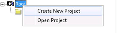
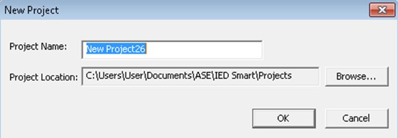
Creating a New Project
ASE61850 IEDSmart IEC 61850 Protocol Simulator provides an option to create projects, add IEDs to the project, and start the entire project or specific IEDs within the project. This provides users to simulate a set of IED / Relays to simulate a substation or just one IED / Relay for testing specific functions.
Adding IED Configuration to Project
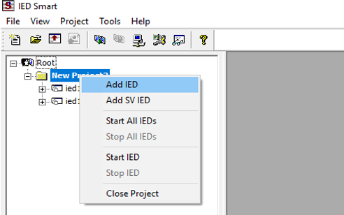
The user can add Individual IEDs to the project. The User also can Load an SCL File, and the IED name and Access point will automatically be updated from the SCL file. Users can create multiple instances of the same server by providing the number of server instances.
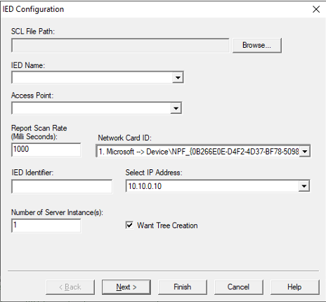
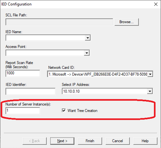
ASE61850 IEDSmart IEC 61850 Server Simulation software allows users to set the Report SCAN rate in a millisecond. Each individual IED can be set with IP Addresses. The Software provides a very unique way for customers to create Virtual IPs and assign these to each IED.
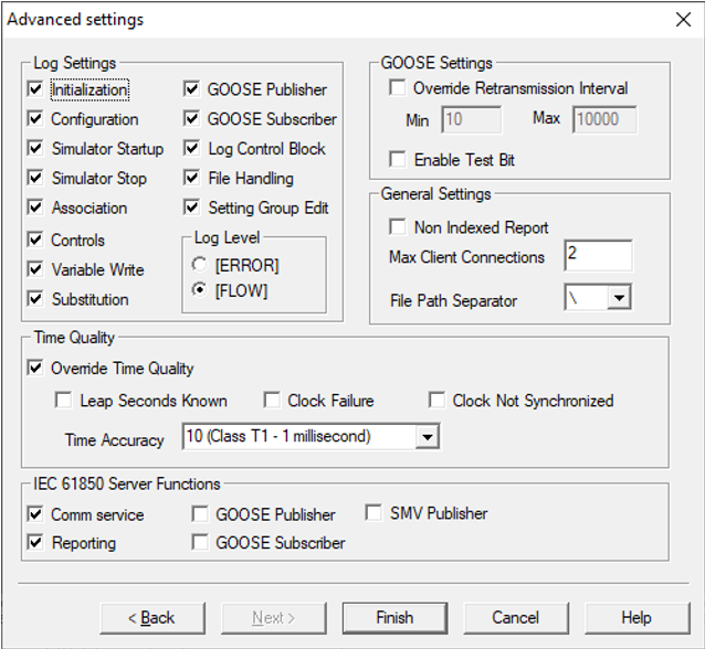
The IEC 61850 Server Simulator software allows you to configure the following advanced settings.
- Log Settings – To configure the IED log
- Log level
- General Settings
- IEC 61850 server functions
- Goose Settings
- Time quality

| Name of the Filed | Description |
| Log Settings | |
| Initialization | Enable/Disable Initialization activities logging. |
| Configuration | Enable/Disable Configuration change events logging. |
| Simulator Startup | Enable/Disable Startup logging. |
| Simulator Stop | Enable/Disable Stopping Activity logging. |
| Association | Enable/Disable Association events logging. |
| Controls | Enable/Disable Control events logging. |
| Variable write | Enable/Disable Variable writes logging. |
| Substitution | Enable/Disable Substitution events logging. |
| GOOSE Publisher | Enable/Disable GOOSE Publisher messages logging. |
| GOOSE Subscriber | Enable/Disable GOOSE Subscriber messages logging. |
| SMV Publisher | Additional Control to Enable/Disable SMV publishing if an SMV simulation file is added and started. |
| Log Control Block | Enable/Disable Log Control Block logging. |
| Name of the Filed | Description |
| File Handling | Enable/Disable File handling logging. |
| Setting Group Edit | Enable/Disable Setting Group edits event logging. |
| Log Level | Users can specify the log levels for debug messages. There are two levels are provided.ERROR: Only the errors during run time operations will be logged.FLOW: All errors as well as program flow during run timeoperations will be logged. |
| IEC61850 Server Functions | |
| Reporting | Enable/Disable Reporting publisher. Users cannot enable reporting without enabling Comm services. |
| Comm Service | Enable/Disable Communication Services. |
| GOOSE Publisher | Enable/Disable GOOSE Publisher. |
| GOOSE Subscriber | Enable/Disable GOOSE Subscriber. |
| SMV Publisher | Enable/Disable SMV Publisher. |
| GOOSE Settings | |
| Override Retransmission Interval | Overriding the Min/Max re-transmission(for GOOSE) values configured in the SCL file with following Min/Max values. |
| Min (GOOSE Re- transmission) |
A minimum interval of GOOSE re-transmission if ‘Override Retransmission Interval’ is checked. |
| Max (GOOSE Re- transmission) |
Maximum interval of GOOSE re-transmission if ‘Override Retransmission Interval’ is checked. |
| Enable Test BIT | Enable/Disable GOOSE Simulation bit. |
| General Settings | |
| Non-Indexed Reports | To force indexed reports to false. This configuration will be applicable only if the tag is missing in the SCL file configuration. If this parameter is not checked, then the tool will work with the SCL file configuration based on the indexed reporting tags in it. If the indexed reporting tag is missing in the SCL file and if this the parameter is not checked then indexed reporting will be enabled by default. |
| File Path Separator | The separator used to separate folder names and Filename of the absolute path of a file. This is applicable only in the case of the file transfer. |
| Max Client Connection | Users can configure the maximum number of Client connections that the Server can support. If User configures 4 client connections, then 5th IEC 61850 Client will not get a connection |
| Time Quality | |
| Override Time Quality | Check this to override the default time quality of IEDSmart with the user-configured values to that IED. |
| Leap Seconds Known | Check this to set the Leap Seconds Known bit in time quality |
| Clock Failure | Check this to set the Clock Failure bit in time quality |
| Clock not Synchronised | Check this to set the Clock not Synchronised bit in time quality |
| Time Accuracy | 5-bit value to specify time accuracy. 0-31 are the possible values |
Advanced Configuration Parameters
| Name of the Field | Description |
| Initialization | Enable/Disable Initialization activities logging |
| Configuration | Enable/Disable Configuration change events logging. |
| Smart Startup | Enable/Disable Startup logging. |
| Smart stop | Enable/Disable Stopping activity logging. |
| Association | Enable/Disable Association events logging. |
| Controls | Enable/Disable Control events logging. |
| Variable write | Enable/Disable Variable writes logging. |
| Settings Group Edit | Enable/Disable Setting Group edits event logging. |
| Substitution | Enable/Disable Substitution events logging. |
| GOOSE Publisher | Enable/Disable GOOSE Publisher messages logging. |
| GOOSE Subscriber | Enable/Disable GOOSE Subscriber messages logging. |
| Log Control Blocks | Enable/Disable Log Control blocks events logging. |
| File Handling | Enable/Disable File Handling events logging. |
| Comm Service | Communication service can be enabled from the Advanced settings window |
| SMV publisher | SMV publisher can be enabled from the Advanced settings window |
| Reporting | Reporting publishers can be enabled from the Advanced settings window. Users cannot enable reporting without enabling Comm services. |
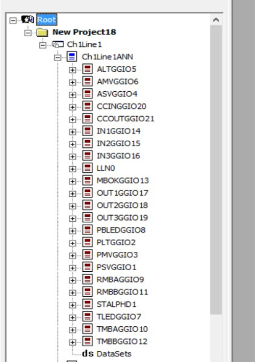
Loaded SCL file can be viewed in the project window in a tree
the form which allows users to view/expand and drill down into
individual objects / LN’s.
Start IED
The user can start all the IEDs in a project, right-click on the project name and select “Start All IEDs” to start
all IEDs in the project.
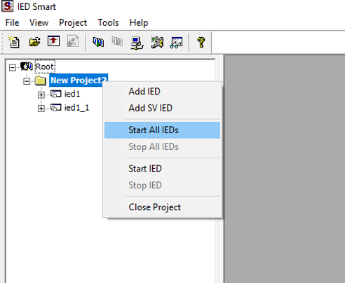
The software allows you to start the servers individually or start the entire project. The status of the project and IEDs are
available in a user-friendly manner.
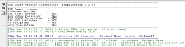
Figure 25: Status of IED
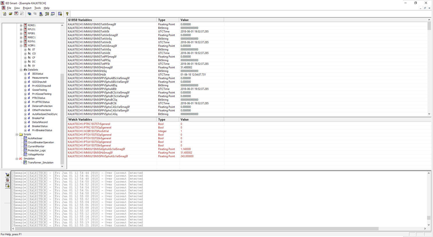
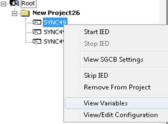
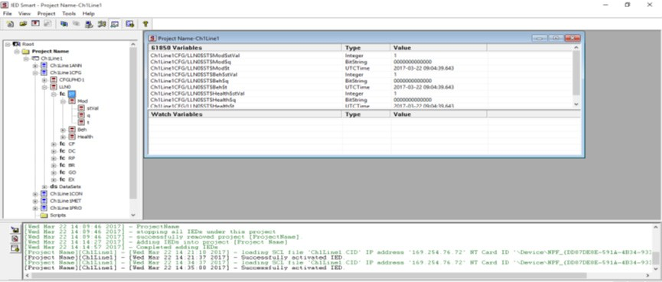
IEC 61850 Variables View
After successfully loading the IEC 61850 standard SCL file, the user can see the Logical Devices ( ), Logical Nodes ( ), Functional Constraints ( ), Data Attributes, and Data Sets ( ) under the “IEC 61850 Variables” window. The contents of each node can be seen in the right pane by clicking on the respective nodes, and their IEC 61850 path, type, and current value will be listed in the 61850 Variables window.
Watch Window
You can use the Watch Window to compare or analyze various variables that belong to different functional constraints (FCs). You can also use the Watch Window to edit the value of a variable. The variables can be added into the Watch Window from the IEC 61850 Variables view window. The selected elements can be deleted from the Watch window by right-clicking on the Watch window and selecting the “Remove” or “Remove all” option.
Global Watch Window
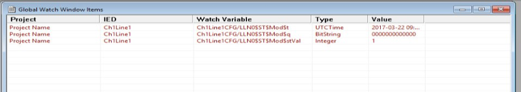
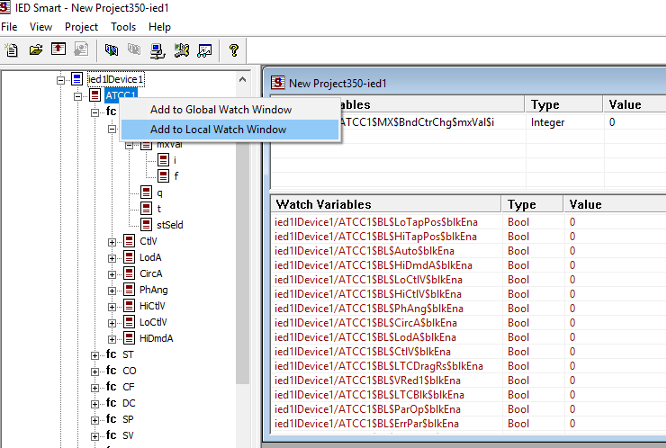
When more than one server in a project and the user needs to watch variables from different servers in a single window, the user can use the Global Watch Window. To add a variable to the Global Watch Window, the required variable must be selected from the project view window, right-click the variable and select the option “Add to Global Watch Window”.
Edit Quality
IEDSmart provides the option to edit the quality of any point.
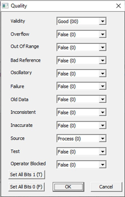
Click on the value cell of the corresponding quality from IEC 61850 Variables View /Local Watch Window/Global Watch Window to get the popup to edit quality. See the image below.
Users can edit any bit in the quality file. Each bit or combination of bits is provided as a Combobox with possible
drop-down values. In addition to that, there are buttons for setting all bits together to 1(true) or to 0(false).
Click on the OK button to save the changes and the Cancel button to cancel the edit.
Edit Time Stamp
If the user needs to simulate a timestamp change for any kind of testing, then IED Smart provides the option to change the
timestamp of a point. In a normal scenario, the time stamp of each point will be the system time taken at the time of the update of the associated data. But if the user opts to edit the timestamp, the time won’t be updated automatically on changing the associated data, but the user entered time will be updated as the timestamp. Edit Time Stamp enables or disables the setting and is independent for each ‘t’ in the variable list. This can be enabled or disabled from the Variable View, Local Watch Window, or Global Watch Widow.
See the figure below.
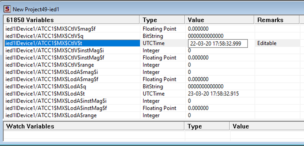
Right-click on each ‘t’ to get the menu shown above and click on Enable Manual Time Stamp Edit. The item will be shown checked once it is enabled. The same menu item can be used to disable the feature by unchecking it. The enabled points will be marked as “Editable” in the remarks column. The “Editable” points will be available for edit on the left button click of the mouse.
Log View
The IEC 61850 server log can be seen in the IED Smart Log view window. IED smart uses different colors of logs for representing different types of operations. In addition, the user can save the log file, clear the log view, and configure the logging properties.
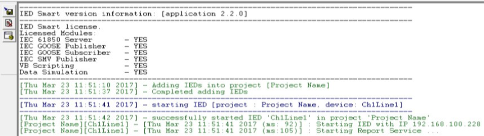 Figure 43: IED Smart Log View
Simulation Files
Users can create simulation files to simulate different substation conditions. The simulation files will be saved as
*.csv (Comma Separated Value) format in the project directory.
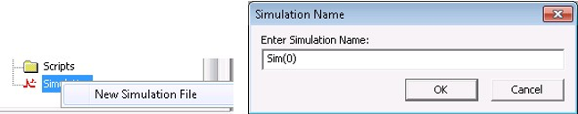
Adding New Simulation File
A New Simulation file can be created by clicking “Simulation-> New Simulation File. The new Simulation file will
be listed below the “Simulation” branch. The user will then be asked to enter a Simulation name as shown in the figure below. Click “OK” to add the Simulation into the project.
Editing Simulation Files
The simulation editor supports the following features:
Insert New 61850 Variables.
Edit Values of the Variables
Configure the time interval for Variables.
Configure whether the values change cyclically or not.
Remove Variables from the Simulation File.
Simulation file properties
“Properties”.
| Property | Description |
| Out of Service | Disable or Enable Simulation |
| Auto Start | The simulation starts when IED starts running |
| Start on User request | The simulation will start only on user request |
Table: Simulation – Additional Options
View SG Settings
To view the SGCB Settings, the user needs to click “server->View SGCB Settings” as shown in the figure. In the figure below, “BCU” is the server.
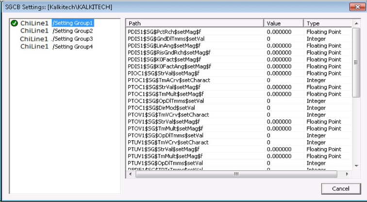
The left tree view shows the settings groups configured in the SCL file. Mark shows the currently active group. Whenever the Setting Group is being modified by the client, it will be marked. The user can see the Settings Group element details by clicking on the respective group names.
View/Edit Configuration
The user can view or edit configuration settings by clicking “server->View/Edit Configuration” as shown in the figure. In the example, “BCU” is the server.
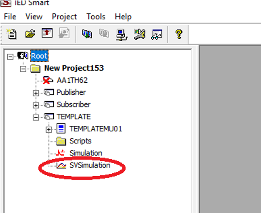
Sampled Value Publisher
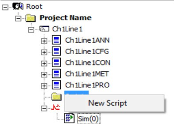
Under every IED added in a Project, there will be an option for SV Simulation. See the below figure. The option is marked with a red-coloured ring.
Right-click on the ‘SVSimulation’ to add a New Simulation File. See the figure below. On clicking ‘New Simulation File,’ a popup window opens. Users can configure the simulation file and click OK. See the figure below. A simulation file will be added under the ‘SVSimulation.’ Double click on the simulation file to get the following window.
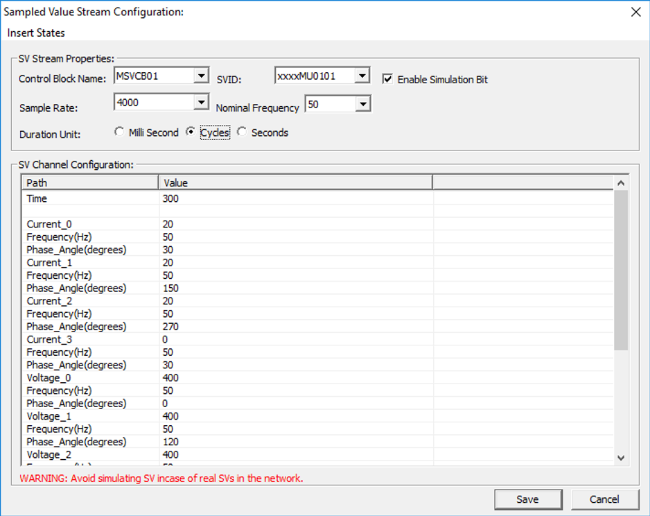
Parameters of Sampled Value Stream Configuration
| Parameter Name | Description |
| Control Block Name | Name of the MSVCB/USVCB. Configured SV control blocks in the loaded SCL will available in the dropdown. |
| SVID | SVID of MSVCB/USVCB. On selecting the SV control block the corresponding SVID will be loaded from SCL. |
| Sample Rate | Sampling Rate of SV |
| Nominal Frequency | Nominal frequency is relevant when Duration is in Cycles. The number of cycles is decided based on Nominal frequency. |
| Duration | Decides if the time duration configured for sampled value publishing is in Milliseconds/Seconds/Cycles |
| Enable Simulation Bit | To enable/disable simulation bit |
| Parameter Name | Description | |
| SV channel Configuration |
SV channel configuration Includes the duration of sampled value publishing and the value used for publishing the samples of each dataset Element. | |
| Parameter | Description | |
| Time | Time duration to which the SV should be published after starting SV simulation. This can be either in Seconds/ MilliSeconds/Cycles. The above mentioned filed “Duration’’ decides the unit of ‘’Time’’. Users can add comma-separated values of ‘time’ along with comma-separated values of Dataset elements. The simulator sends samples based on the fist value of each dataset element for a duration configured first and then with the second value of each dataset element for a duration configured second and so on. | |
| Dataset Element Current/Voltage | Any valid dataset element of MSVCB/USCVB will have an entry under ‘’SV Channel Configuration”. The user is supposed to enter the RMS value of Im/Vm of the sine wave expected to be generated. |
|
| Frequency | Frequency of the sinusoidal signal for the corresponding current/voltage signal |
|
| Phase | Phase shift from the previously mentioned signal. | |
Table: SV Stream Configuration Parameters
Start or Stop SV simulation
ASE61850 IEDSmart supports Sampled Value Simulation and provides features for Starting and Stopping an SV Simulation.
SV IED Properties
| Parameter | Description |
| Start Discovery | On Clicking this button, the IED start searching for incoming SV packets and show the available publishers in the network. See figure-61 shown below. |
| Save as PCAP | This enables to save the subscribed file in PCAP format |
| Save as COMTRADE | This enables to save the subscribed file in COMTRADE format |
| Start SV subscription | Select any of the discovered SVID and click on this button tosave the file as PCAP/COMTRADE |
| Subscription Duration in Seconds | This is the duration of subscription in seconds |
| Network card ID | Network Interface card though which it accepts the subscription |
| SV Subscription filename | Filename to which the samples to be saved |
| SV Subscription files are saved at: | This shows the location at which the file is saved. The file locationis not editable. |
| Load PCAP | The SV IED can act as a publisher also. A PCAP file with SVpackets shall be loaded, selected, and transmitted. |
| Start | This is the start button to transmit packets in the PCAP file forthe selected SVID. |
| Packet details | Here show the SVIDs available in the loaded PCAP. Users can select any SVID and start publishing. |
Script-based Simulation
The software has a robust scripting interface that helps write your own scripts to simulate values for the IEC 61850 Server for each Individual IED or Relay in a project.
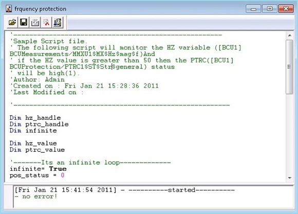
The table below shows some of the functions used in the scripts.
| Function name | Description |
| GetVariableHandle | Returns the handle of an IEC 61850 Variable. Handle = GetVariableHandle(“variable name as string”) Parameters: IEC 61850 Variable name Returns: On error, this function will return -1 otherwise >= 0 Sample: Dim handle handle = IEC61850.GetVariableHandle(“BCUMeasurements/ MMXU1$MX$Hz$mag$f”) |
| ReadVariable | Returns the value of an IEC 61850 variable. Parameters: IEC 61850 Variable handle. Returns: The current value of an IEC 61850 Variable. Sample: Dim value Value = IEC61850.ReadVariable(handle) |
| WriteVariable | Writes a value to an IEC 61850 Variable. Parameters: Handle – Handle to IEC 61850 Variable Value – Value to be written to the variable. Returns: On error this function will return -1 otherwise 0 Sample: Dim handle, Value Value = 10 IEC61850.WriteVariable Handle, Value |
| SleepExecution | Makes the function idle for a user-defined number of millisecondsParameters:Time in milliseconds. Sample: IEC61850.SleepExecution(1000) |
| Trace | Displays the trace messages on the log view of the smart Parameters: String. Sample: IEC61850.Trace(“sample message.”) |
Table: Scripting – Functions List
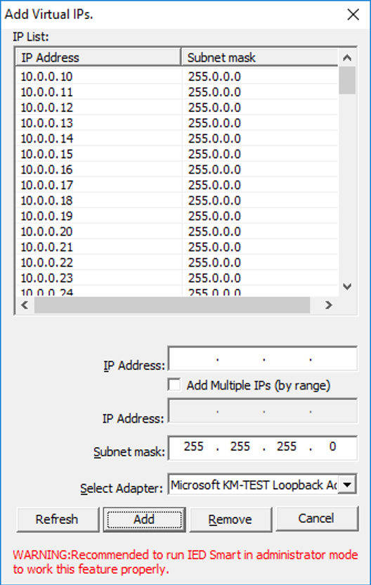
Creating Virtual IPs
ASE61850 IEDSmart enables creating and testing 100’s of IEDs with a unique IP address to simulate a real substation with the Virtual IP capability. Users can create Virtual IP’s and assign them to the IEDs.
Edition 2 Index Option
Edition 2 supports “Indexed = false” operation. This specifies the maximum number of clients that can be connected is limited to 1, and the user doesn’t want to add the index to the RCB name. The ASE61850 IEDSmart supports this feature.
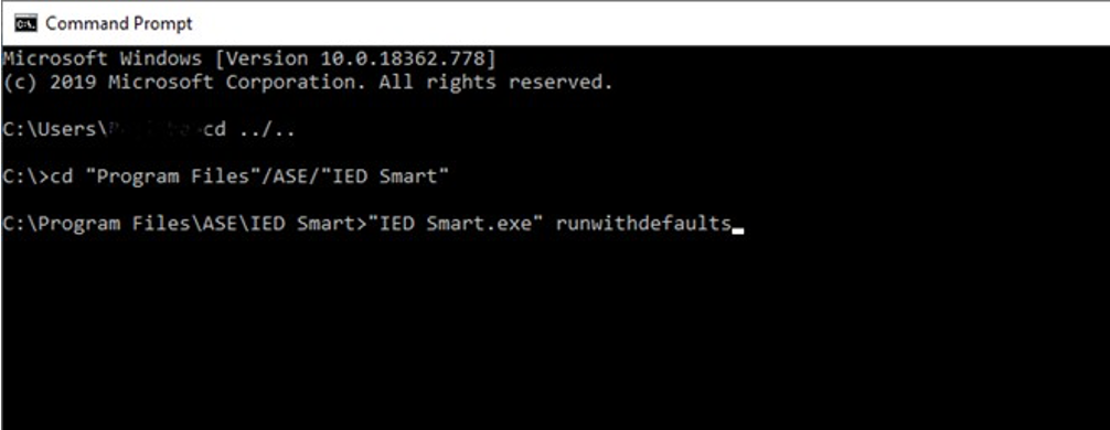
Command Line Execution
ASE61850 IEDSmart can be run from a command-line argument to support an unattended application launch for automated testing.