Overview
ASE’s protocol and communication test products, first introduced in 1989, are currently in use worldwide by RTU and IED equipment manufacturers, electric power utilities, DER developers, Renewable Power Generation companies, SCADA system vendors, Inverter and Battery Manufacturers to test DNP3, IEC 60870-5-101, IEC 60870-5-103, IEC 60870-5-104, IEEE 2030.5, SunSpec Modbus, Modbus, IEC 61850 and 80+ other protocols.
All ASE2000 Protocol Simulator and Test Set helps you troubleshoot SCADA / RTU, IED and DER protocol communications and equipment behavior in the field or in the control center or cloud. All ASE2000 licenses comes with its entire library of protocols. You do not need to buy separately each protocol. When you buy a license of ASE2000, in addition to getting access to testing, troubleshooting and simulating 80+ protocols in real-time, you also get the ability to listen or monitor protocol traffic for all protocols, the ability to parse protocol traffic files and analyze protocol behavior.
ASE2000 comes with the following standard protocols like DNP3 Client and Server Simulator, DNP3 Serial and TCP/IP, IEC 60870-5-101 Master and Slave Simulator, IEC 60870-5-103 Master and Slave Simulator, IEC 60870-5-104 Client and Server Simulator, Modbus Serial and TCP/IP Master and Slave Simulator, IEEE 2030.5 Client and Server Simulator, SunSpec Modbus Master and Slave Simulator, SEL Fast Message among many others.
ASE2000 also comes with the following legacy protocols like CDC Type I and II, CONITEL (multiple variations), Telegyr 8979, Harris 5000, Harris 6000 and over 70+ legacy protocols. Full list of supported protocols is available here
Read MoreAll protocols are supported in a single program with a single user interface, so that you can test or simulate or monitor or listen DNP3, IEC 60870-5-101, IEC 60870-5-104, IEC 60870-5-103, CONITEL, CDC, and more with the same software. The ASE2000 provides a total solution approach to the area of protocol test equipment software and its family of PC-based protocol test equipment that includes USB serial communication hardware and Bell-202 modems.
ASE2000 Version 1 was first introduced in 1999 (replacing older Comm/32 and Comm/64 models) and has a current installed base of several thousand units in numerous utilities and SCADA industry companies worldwide. Version 1 testset supported DNP3, IEC 60870-5-101, IEC 60870-5-104, and 80+ protocols. It continues to be used as the preferred DNP3 Protocol Testset or DNP3 Protocol Simulator.
ASE2000 Version 2 Testset, introduced in September 2011, expands on Version 1 features by supporting operation in Exchange and Task modes. Exchange mode implements Version 1 features and operation. Task mode, new in Version 2, adds a simplified means to perform a set of common tasks such as device initialization, data acquisition, controls, and file transfers. Task Mode operation requires only that the user select an RTU/IED device and a task to be performed. Communication message editing, frequently required in Version 1, is automated in Version 2. Version 2 supports DNP3, IEC 60870-5-101, IEC 60870-5-104, and 80+ protocols. Today, Version 2 is the most preferred DNP3 Protocol Testset, DNP3 Protocol Simulator, IEC 104 Protocol Testset, and IEC 60870-5-104 Protocol Simulator.
ASE2000 Version 2 Testset
The ASE2000 RTU Testset is a full-featured DNP3 protocol simulator, IEC 60870-5-104 protocol simulator, IEC 60870-5-101 protocol simulator, 80+ Legacy protocol simulators, and test set, which provides the user with a powerful and flexible tool for testing and maintaining SCADA RTU and SCADA IED equipment and diagnosing communication problems.
User Interface
ASE2000 operation is a menu-driven, window-oriented interface, developed in line with standard Windows interface presentation guidelines. Set-up screens allow the user to define test session-specific information and user preference information. For quick-start operation, the supplied default values for most test operations are sufficient and preclude the need for lengthy and complicated pre-test set-up. For tests that do require special conditions, a set of intuitive and easy-to-use set-up screens is provided. Special set-up conditions can be saved to uniquely named files and easily retrieved for use in future sessions. Many users develop a library of frequently used test scenarios with this feature, thereby eliminating repetitive set-up for future test sessions.
Display Options
Display screens provide dynamic data display during monitoring and simulation mode test sessions.
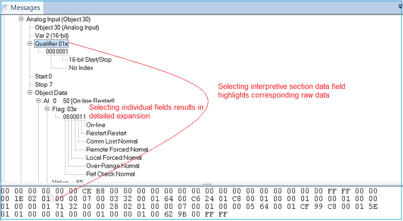
Users are not limited to a single display format for message data. In addition, message data can be displayed in Interpretive Mode, which identifies, in English, the various message elements and their values, Raw Data Mode, which displays only the numeric message data, or both. Point data is available for presentation in tabular format.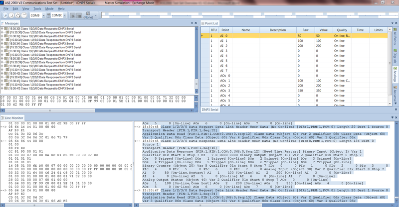 |
The Line Monitoring view in Versions 1 and 2 shows communication line data in raw and interpretive styles. Clicking on a field or value on one side highlights the corresponding field on the other side. |
| The Messages View in Version 2 presents communication line data in an alternate format with “zoom-in” details
|
| The Point Values View in Versions 1 and 2 shows point names, values (raw and scaled), quality codes, and times
|
Modes of Operation (Version 1 and Version 2/Exchange Mode)
The ASE2000 test set has three modes of operation: Master Simulation (communicating to a downstream device or RTU), RTU Simulation (communicating to a master station), and Line Monitor (listening to communications between Master and RTU/IED devices).
Master Simulation Mode provides the capability to issue data scan requests and supervisory control commands to one or more RTU’s on a communication line. The set-up screens for this mode allow the user to define a test scenario that identifies which device(s) to communicate with, which commands to issue for each device, frequency of commands, screen format and display format of message data.
This implies, for Eg: if you are using ASE2000 as a DNP3 Protocol Testset, you can select the protocol as DNP3, select the RTU Simulation mode, and run as a DNP3 RTU or Outstation.
RTU Simulation Mode allows the user to configure the ASE2000 RTU test set as one or more RTUs to respond to data scan requests and supervisory control commands. Convenient set-up menus allow the user to specify point types, number of points, and point order that will result in the proper data message structure. Point modeling can also be enabled to provide data value changes on successive data scans.
This implies, for Eg: if you are using ASE2000 as an IEC 60870-5-104 Protocol Testset, you can select the protocol as IEC 104, select the RTU Simulation mode, and run as an IEC 104 RTU.
Line Monitoring Mode is used to monitor communication between a master station and all RTU/IED devices on a communication line. Message data for both directions is shown. Line monitoring is available for Serial Bit / Byte and Network protocols. If you are running ASE2000 as a DNP3 Protocol Testset or IEC 60870-5-104 Protocol Test Set in monitor mode, you can listen on the network and see the DNP3 or IEC 104 protocol traffic in the network and see the traffic and exchanges between SCADA and RTU.
Modes of Operation, Version 2 Task Mode Enhancements
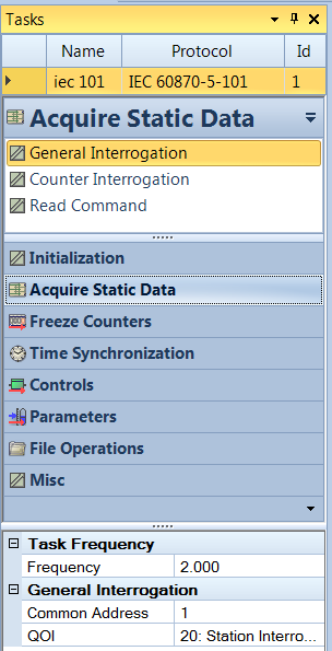
ASE2000 Version 2 adds Task Mode. In this mode, the ASE2000 operates from a user-defined RTU/IED device database. Each definition includes counts and addresses of all input points at that device.

Task Mode/Master Simulation provides the user with a set of tasks applicable to the protocol of the selected device. Activating a task causes appropriate messages to be built and transmitted to accomplish the selected task for the device’s protocol and point configuration. Task Mode Master Simulation supports DNP3 Protocol Simulation, IEC 60870-5-101 Protocol Simulation, IEC 60870-5-104 Protocol Simulation, and most other ASE2000 protocols simulation.
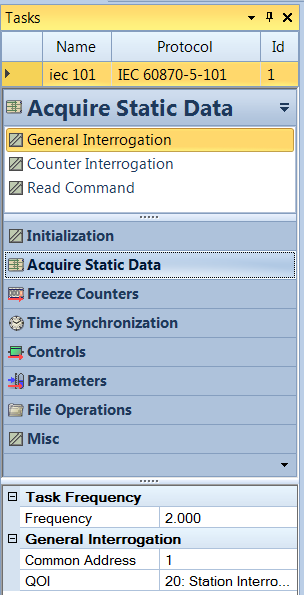
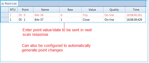
Task Mode/RTU Simulation allows individual points states/values to be entered from the Point Values view. New values are transmitted in the next applicable scan response, with timestamps if appropriate to the protocol. In addition, the user can define point modeling parameters to automatically generate point changes. Task mode RTU simulation supports DNP3, IEC 60870-5-104, IEC 60870-5-101, and most other protocols supported by ASE2000 Test Sets.
Advanced Features
A number of advanced features are available for specialized test requirements.
Event Logging generates a text file recording significant events, including:
– High/low limit alarms for selected analog input points
– State changes for selected digital input points
– Communication errors
– Detection of specific communication messages, such as trip/close commands
– Online communication can be triggered to stop when a selected event is detected, thereby creating a record of communication activity prior to the event
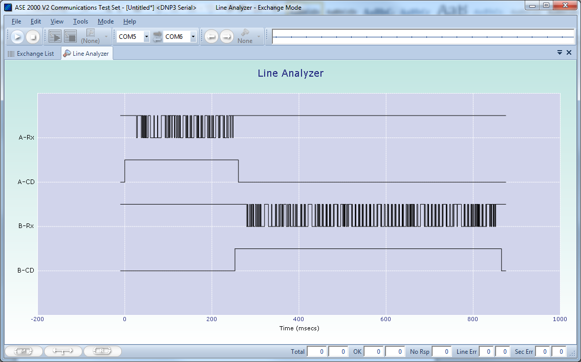
Signal Analysis is available to users with an ASE-supplied communication device (BCOM-USB) and provides a plot of bidirectional carrier and data signals to 0.1-millisecond resolution.
DNP3 Certification testing support files are included with the ASE2000 Version 2 software at no additional charge. An automated test results report can be generated through a standard browser.
DNP3 Transport Certification Test Results
| DNP3 Test Number | Title | State | Failure Reason |
| 7 | DNP3 Transport Layer | Pass | |
| 7.2 | DNP3 Test Procedure | Pass | |
| 1 | Cycle power to the DNP3 DUT. | Pass | |
| 2 | DNP3 Request Class 0 data (Object 60 Variation 1) using Qualifier Code 0x06. | Pass | |
| 3 | Verify that the DNP3 DUT responds with a valid message. | Pass | |
| 4 | If the DNP3 DUT’s reply contains more than 249 octets, then verify that the first response message sets the FIR bit to a one, the FIN bit is set to zero. | Pass | |
| 5 | Verify subsequent DNP3 messages to assure that the FIR bit is zero, the FIN bit is zero, and the sequence number increments by one. | Pass | |
| 6 | Verify that the last DNP3 message has the FIR bit is zero and the FIN bit is one, signifying the last data fragment, and the SEQ value increments by one. | Pass | |
| 7 | If the DNP3 DUT’s reply contains less than 250 octets in the Data Link Frame, then the FIR bit is set to one, and the FIN bit is also set to one. | Pass |
Features & Specifications
- Graphics window/menu screen presentation with keyboard or pointer navigation
- Common user interface set-up displays, independent of protocol
- Custom display of data with protocol-specific formatting
- User preference set-up and save
- Extensive On-Line help facility
- Supports 32-bit and 64-bit Windows 7, 8, 10, XP (SP2, SP3), Vista
- Real-time, time-stamped display of message data
- Interpreted and raw data display
- Display filtering options
- Event triggering
- Disk storage/retrieval of message data from test sessions. Files can be sent to anyone for use with a free viewer available to non-ASE2000 users
- Communication statistics (message count, parity errors, security errors, etc.)
- Data and control requests to one or more devices
- ASE2000 defined test scenarios
- User-defined test scenarios
- IEC 60870-5-104 Protocol Simulator
- DNP3 Protocol Simulator
- IEC 60870-5-101 Protocol Simulator
- Bit / Byte Protocol Simulator
- Legacy Protocol Simulator
- User-configurable to respond to master requests for multiple devices (party line)
- Point value modeling for data change activity (analog, digital, accumulator)
- IEC 60870-5-104 Protocol Simulator
- DNP3 Protocol Simulator
- IEC 60870-5-101 Protocol Simulator
- Bit / Byte Protocol Simulator
- Legacy Protocol Simulator
- IEEE 2030.5 Client Support in Exchange mode
- Large scale simulation of Aggregators and Direct Clients in the same session / instance
- Automatic Configuration creation (one to many) from template files
- Responses automatically update links and parameters for the next requests to reduce manual configuration.
- CSV simulation for Mirror Usage points
- Full support of telemetry updates starting from Device Capability
- 2030.5 Certificates support – Sunspec / Private Certificates can be imported into the tool.
- Supports DNP3 and SunSpec Modbus / Modbus Protocols for UL 1741 SB / IEEE 1547 – 2018 protocol testing
- User-configurable event log for communication errors, analog limit exceptions, digital point changes, selected message types (supervisory control)
- Event triggering
- RTU response time measurement (1 msec. resolution using ASE’s BCOM-USB device)
- Low-level control over message structure, security error, message timing, and other fields to allow customization for advanced testing requirements
- Communication error generator for error detection testing
- Certification testing scripts
- Secure authentication support
- Automated file transfer procedures
Hardware Configuration
The ASE2000 RTU Testset is available in various models that differ only by communication hardware; the software is identical. The ASE2000-COM supports Asynchronous Byte and Network protocols only. Standard PC COM ports cannot support bit-oriented communication used by many of the older legacy protocols.
ASE2000-USB-RS
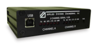
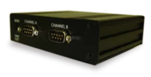
The ASE2000-USB-RS supports all asynchronous serial, synchronous serial, and network protocols. Serial communication is supported through ASE’s BCOM-USB, a USB bus-powered, two-channel, serial RS-232 communication device. The two RS-232 ports support both synchronous (bit protocol Eg: CONITEL) and asynchronous (byte protocol Eg: DNP3, IEC 60870-5-101) communication. A set of RS-232 LEDs for each channel show TX, RX, RTS, CTS, and CD status. Connection to the PC is via a standard USB device cable. Both USB 2.0 and USB 1.1 standards are supported. RS-232 communication operates from 50 to 56K baud for byte-oriented protocols and from 50 to 2400 baud for bit-oriented protocols. Network protocol communication uses standard PC network hardware (Eg: DNP3 TCP/IP or for IEC 60870-5-104). For network protocols, the BCOM-USB device provides the license. That is, the ASE software will not operate without the BCOM-USB device inserted, although it is not actively involved in network communication. An upgrade path to the BCOM-USB device is available to users of ASE’s older PCMCIA card or for an upgrade from an ASE2000–COM model. Upgrade requires the return of the current hardware (PCMCIA card or dongle) within sixty days after delivery of the BCOM-USB device.
ASE2000-USB-M
Model ASE2000-USB-M includes all the hardware provided in the ASE2000-USB-RS, plus a dual-channel Bell-202 modem. The modem is powered by the BCOM-USB device. The same software is provided for the model ASE2000-USB-M as for the model ASE2000-USB-RS. So all your popular protocols, like DNP3, IEC 60870-5-104, and IEC 60870-5-101, will continue to work with ASE2000-USB-M.
ASE2000-COM
The ASE2000-COM utilizes standard PC COM ports and is suitable for users that require support for asynchronous byte-oriented and network protocols only, all using standard PC hardware or USB to serial devices manufactured by others. The ASE2000-COM model:
- Supports only asynchronous byte and network protocols. This includes protocols such as DNP3, IEC60870-5-101, IEC60870-5-103, IEC60870-5-104, and Modbus
- It does not support ASE’s dual-channel Bell-202 modem since that modem derives its power from the BCOM-USB device. The COM model will operate with an external modem. ASE sells single-channel external Bell-202 and V.23 modems.
- Does not support the Line Analyzer function
- Does not support modem timing properties (pre-transmission mark, post-transmission mark, and receiver squelch times)
- All ASE2000 models require two COM ports to support serial protocol Monitor Mode operation. Users who wish to operate in Monitor mode should verify that their computer is equipped with two serial ports. (ASE’s BCOM-USB device does contain two serial ports).


